Automatic and Manual Temperature Control unit Circuit Diagram These scientific discoveries have created the basis for developing modern temperature sensors, many of which are high-technology and can be integrated into automated systems. In the next sections, we will review the physics behind temperature measurement and some of the most common types of temperature sensors. According to the different control loops, PID temperature controllers can be divided into two types: single-loop and multi-loop. A single-loop temperature controller can only have 1 input and 1 output, and is generally used to control 1 temperature point.

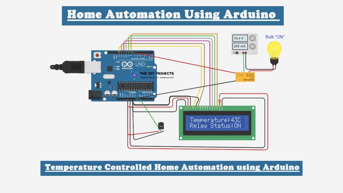
Temperature sensor LM35 and Arduino Uno are the hardware used interfaced with computer, and the temperature is controlled in the room. Automatic temperature control system is an important
PDF Microcontroller based Temperature Controller System Circuit Diagram
Controller (PIC) based automatic temperature control system is applied to upgrade the functionality to embed automation feature. to the temperature falls below the specified limit. The system monitors the temperature from the thermocouple temperature sensor, where it will control the electric heater according to the setting values in the Establish the Target Temperature: To set the Target Temperature, utilize the controller's interface to set your desired setpoint temperature - this is what the controller will maintain over time. 2. Adjusting PID Parameters: PID parameters (Proportional, Integral and Derivative) need to be set appropriately to attain optimal control.

The major parts of the feedback control system are built into the Temperature Controller. A feedback control system can be built and temperature can be controlled by combining a Temperature Controller with a controller and temperature sensor that are suitable for the controlled object. Therefore, this work involved the use of the PLC-based fuzzy PID control technology, by which the system temperature was set through the fan and the heating plate to control the box temperature. 2 System design. In this design, the temperature control system consists of hardware and software components. 2.1 System hardware

Automatic Temperature Control System Using PIC Microcontroller Circuit Diagram
LM35 Temperature Sensor: Connect the VCC pin of the LM35 to the Arduino's 5V pin, GND to ground, and the output to the analog pin A0.This sensor will send temperature readings to the Arduino. Heating Element: Connect the positive terminal of the 12V power supply to one of the terminal of the heating element.Connect the other terminal of the heating element to the drain of the MOSFET
