PDF Design and Implementation of Arduino Circuit Diagram Follow the steps in this tutorial to bring this magical gesture-controlled robot to life and leave a lasting impression on your audience. If you are interested in more gesture controlled projects, you can check out the below . 1. Gesture based light control. 2. Gesture controlled Robotic Arm. 3. Gesture controlled Video Player. 4. The module comes with the gesture recognition algorithm and provides simple and reliable data output. Use the sensor to directly communicate with upper computer or micro-controllers like Arduino and Raspberry Pi via serial port. It works on the principle of infrared detection, the hand motion is monitored using an infrared led and sensing system. gesture, proximity, light color and light intensity sensor : estimate the room's luminosity, but also whether someone is moving close to the board; Wiring. Code. This project utilizes the Arduino_APDS9960 library which enables the use of gestures. In the Arduino IDE, navigate to tools, manage libraries and proceed to install the library.
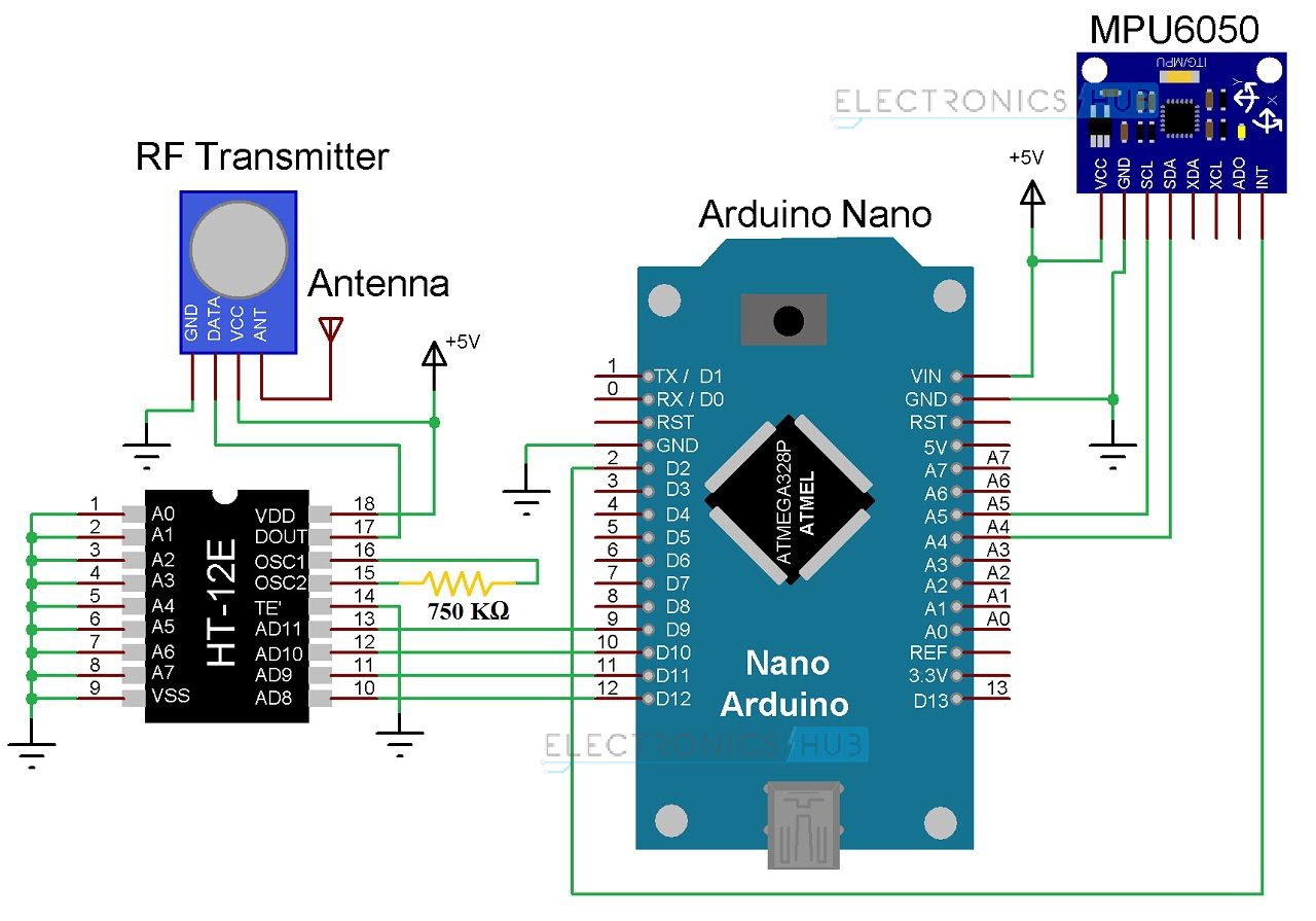
For Gesture controlled robot using Arduino, the complete code is available here. Below we are explaining the program line by line. Transmitter Side Program. In this program, Arduino reads the data from MPU6050 and sends it to nRF 24L01 transmitter. 1. Begin the program by adding the required library files. A gesture-controlled robotic arm is a robotic system that moves in response to hand gestures. Instead of using buttons or joysticks, an accelerometer sensor detects hand movements and sends signals to an Arduino robot arm, which then moves accordingly. This technology is used in automation, rehabilitation, and even remote-controlled operations.

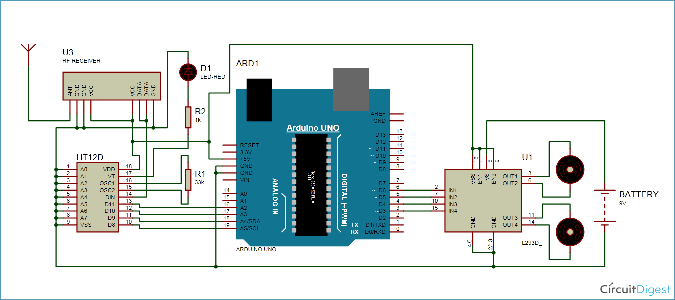
Gestures Project Circuit Diagram
Today, we are going to build an exciting robotics project where an Arduino-based robot car is controlled using the MPU6050 sensor (Accelerometer & Gyroscope) and Bluetooth communication. The MPU6050 sensor will detect hand movements and translate them into motion commands, which will be sent via an HC-05 Bluetooth module to control the robot This project shows how to connect nRF24L01 Radio Module and MPU6050 with Arduino for projects that require Gesture Control
Start Visuino as shown in the first picture Click on the "Tools" button on the Arduino component (Picture 1) in Visuino When the dialog appears, select "Arduino UNO" as shown on Picture 2 Step 4: In Visuino ADD and Set Components The gesture sensor sense the hand direction for Right to Left, Left to Right, Up to Down, Down to Up, Near to Rar, Far to Near. Arduino has an interface with APDS-9960 and 4 channel relay, These gesture commands to control the relay. The relay for controlling LED light by using HAND GESTURE. The output status is displayed through the LCD display.